mirror of
https://github.com/uhi22/pyPLC.git
synced 2024-09-11 00:38:29 +00:00
133 lines
10 KiB
Markdown
133 lines
10 KiB
Markdown
# EvseMode
|
|
|
|
This document describes how to use the pyPlc project as a charging station. The possible use cases are to really charge a car via CCS (which requires a lot of additional power-electric hardware), or to investigate whether it is possible to draw energy out of the cars CCS port.
|
|
|
|
Discussion here: https://openinverter.org/forum/viewtopic.php?t=3551
|
|
|
|
## Hardware
|
|
|
|
To convince the car, that a CCS charger is connected, several preconditions need to be fulfilled:
|
|
* PP resistor: Between the ProximityPilot and PE (Ground) we must connect 1.5kOhms resistor.
|
|
* CP signalling: The ControlPilot needs to be pulled to 12V over 1kOhms. If the car pulls the CP down to 9V, we must provide a PWM with 1kHz, 5% width, plus and minus 12V amplitude via 1kOhm resistor. Basically the CP signalling is the same as in a standard AC wallbox, the only difference is the fix 5% PWM ratio. As wallbox controller I used an arduino, similar to https://www.instructables.com/Arduino-EV-J1772-Charging-Station with the software https://github.com/uhi22/WallboxArduino, and the poti on left border to select 5% PWM.
|
|
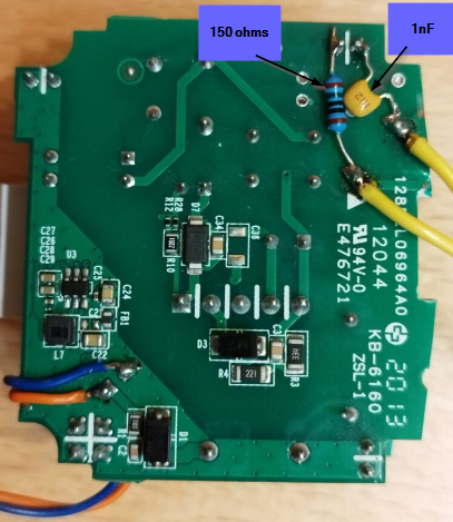
* Homeplug communication: The car wants to establish high-level communication on the CP line, using the HomePlug standard. We connect a modified homeplug modem between the CP and PE, with coupling network e.g. 150 ohms and 1nF in series, to not disturb the 1kHz PWM too much. The modification of the modem is shown in [Hardware manual](hardware.md)
|
|
* On the ethernet port of the HomePlug modem we connect a computer which handles the high level communication. This may be a Windows10 laptop or a Raspberry or similar.
|
|
* We need a power supply for the HomePlug modem and the Arduino-charging-logic, e.g. an USB power bank.
|
|
|
|
## Software
|
|
|
|
### Configuring the HomePlug modem as Charging Station
|
|
|
|
The homeplug modem needs a special configuration, to support the features which are needed for a charging station. We need to write a special configuration file to it. This is necessary only once, the modem will store the settings non-volatile.
|
|
Details in readme.md chapter "Configuration of the PLC adaptor"
|
|
|
|
### Installing pyPlc and openV2Gx on the computer
|
|
See [Raspberry installation manual](installation_on_raspberry.md) or
|
|
[Windows installation manual](installation_on_windows.md)
|
|
|
|
## First run into charging loop
|
|
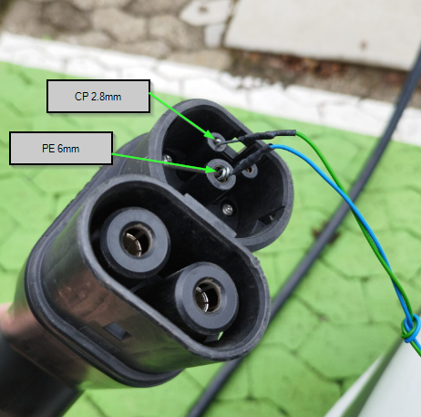
Notebook is connected via Ethernet cable to the homeplug modem. The homeplug modem and the arduino-charging-logic is supplied by an USB power bank. The PE from the car is connected to ground of the homeplug modem and ground of the arduino-charging-logic. The CP of the vehicle is connected to the hot side of the homeplug modem and the hot side of the arduino-charging-logic. The PP of the car is connected to PE via 1k5 (inside the plug).
|
|
On the laptop, just run `python pyPlc.py E`.
|
|
|
|

|
|

|
|
|
|
|
|
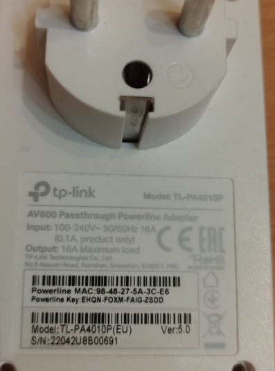
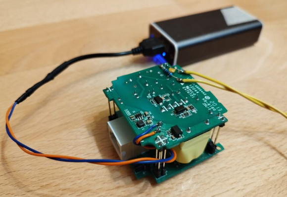
### TPlink TL-PA4010P
|
|
This adaptor was suggested by https://openinverter.org/forum/viewtopic.php?p=37085#p37085 and there,
|
|
successfully used to establish a communication to the CCS charger.
|
|
|
|
|
|
|
|
|
|
|
|
|
|
|
|
|
|
Pro:
|
|
* Can be configured as pev and as EVSE, using two different configuration files (created and patches with github.com/qca/open-plc-utils)
|
|
* Is able to transmit and receive the SLAC messages, if the special config files are used.
|
|
|
|
Contra:
|
|
* In original parametrization, does not support SLAC (not routed from RF to Ethernet, and not vice versa).
|
|
* Depending on the configuration, only one direction of the SLAC is routed from RF to Ethernet. Means: Not suitable for sniffing the complete
|
|
SLAC sequence.
|
|
|
|
Power supply: Originally, it has 12V internal supply. There is a DC/DC step down converter included, which supplies the chipset with 3.3V.
|
|
Works on the original 12V supply line also with 13V/110mA, 10V/120mA, 6V/190mA, and, which reduced RF output power, down to 5V/220mA and even 4V/240mA.
|
|
Just supplying 5V from an USB power bank at the original 12V line works fine. The only drawback is a slightly reduced transmit power, because
|
|
the RF transmitter is connected to the 12V, but is is no issue, because it has anyway much too much transmit power for the CCS use case.
|
|
|
|
How to modify:
|
|
- remove the housing
|
|
- remove the AC power connector parts
|
|
- connect cables to supply the device. Works with 12V, also works with 5V from an USB power bank.
|
|
- connect cables and circuit (1nF and 150ohms in series) for connecting to the pilot line.
|
|
|
|
## Controller for the PEV
|
|
|
|
Besides the homeplug modem, there are additional parts necessary for a vehicle to perform CCS charging. Two of these are: 1. The inlet voltage measurement. 2. The control of CP state and relays.
|
|
|
|
### DieterHV
|
|
|
|
This is the high-voltage Dieter. It is responsible to measure the CCS inlet voltage. DieterHV is an Arduino Pro Mini, running the software from https://github.com/uhi22/dieter, and DieterHV has a quite simple task: Measure the divided voltage from the CCS inlet, and write the output of the ADC to the serial line, with 19200 Baud. The hardware includes a 5V-to-5V-DCDC converter (e.g. B0505S-1W) and a PC900V optocoupler. In the current version, the ADC0 is the main channel, and the ADC1 gets half of the voltage and may be used for plausibilization. Potential improvement could be, to enable also negative voltage measurement, to be able to detect wrong polarity.
|
|
|
|

|
|

|
|
|
|
### DieterLV
|
|
|
|
This is the low-voltage Dieter. It controls the ControlPilot state, by switching an additional 1.2kOhm resistor in parallel to the permanently connected 2.7kOhm. Additionally, the DieterLV controls two relays via simple drivers. In the demo, these relays connect the DC from the CCS inlet to a light bulb.
|
|
Also DieterLV is an Arduino Pro Mini, and it is running the same software as DieterHV. It receives the output control requests via serial line with 19200 Baud, and sets its digital outputs accordingly.
|
|
|
|

|
|
|
|
### OLED Display
|
|
|
|
To show the status, the voltage and the SOC in PEV mode, there is an OLED display connected to the serial line of the USB-to-serial-converter.
|
|
The display is programmed to receive data via serial line and show three lines. The python script is using the function self.hardwareInterface.showOnDisplay(s, strAuxInfo1, strAuxInfo2)
|
|
to fill these three lines on the display.
|
|
|
|
The display is an ESP32-powered board named "WIFI_KIT-32", available e.g. from
|
|
https://de.aliexpress.com/item/1005002931025729.html?spm=a2g0o.productlist.main.23.3d607f4fVNGcAr&algo_pvid=338e0303-b3b2-45c7-94b6-4a55bba4009e&algo_exp_id=338e0303-b3b2-45c7-94b6-4a55bba4009e-11&pdp_ext_f=%7B%22sku_id%22%3A%2212000022853967835%22%7D&pdp_npi=3%40dis%21EUR%2113.87%2111.37%21%21%21%21%21%402100b78b16774931785037679d0714%2112000022853967835%21sea%21DE%210&curPageLogUid=TGlYiLzgZW4i
|
|
|
|
The arduino sketch is available at https://github.com/uhi22/SerialToOLED
|
|
|
|
The connection is simple: The 5V from the USB-to-Serial-converter board are supplying the WIFI_KIT-32, and the TXD of the USB-to-Serial-converter goes via an 1k5 protection resistor to a digital input of the WIFI_KIT_32.
|
|
|
|

|
|
|
|
|
|
### USB
|
|
|
|
Both, DieterHV and DieterLV communicate with 5V serial line with 19200 Baud. To connect these to the Laptop or Raspberry, we use a cheap USB-to-Serial converter with CP2102, similar to https://www.ebay.de/itm/122447169355?hash=item1c826b874b:g:PKYAAOSwBoVjdS28&amdata=enc%3AAQAHAAAA4IQcw6se5g1eqWsesz2sVJybly8WfWQrHcT%2BKk2kbf3dRjRl5Iimf8p54m2HcnGpjpFaTQqdKE0wrxuPJYLQcmOtofOYlAbClGhlgeIn21NQPaCGzqCSAMAI6yXqfsfCpsBZtJe1%2BfAfIOq1kEPDJBbWD6UFAv6%2FhR%2B6WxeiQKeaVSwc%2BRs87aBn0XbtWmF2p0C9RTURpWQauDpaWLsAthbiVBqBjeNkPQxMSx1AMUa33bO0OZakXjXyHVrGhEXRO7952z1oHjKyl51E0YX7Jqb5hA7GhAs%2BUGvPnBAbjKnH%7Ctkp%3ABFBMipSf-Kdh
|
|
Its receive path is feed by the DieterHV via optocoupler, and its transmit path is connected to the DieterLV via a protection resistor.
|
|
On software side, the python module hardwareInterface.py handles the communication with the serial devices.
|
|
|
|
## CCS Detector
|
|
|
|
In some cases it may help to "hear" the CCS communication, to understand what is going on. For this, a detector receiver can be used,
|
|
e.g. this one:
|
|

|
|
|
|
By placing the antenna near to the charging cable and just listening, it is possible to differentiate the following cases:
|
|
* Silence: No communication is going on. No homeplug coordinator is present. No 1kHz PWM is present.
|
|
* Continuous uniform rattling noise: Homeplug coordinator (charger) is there. Depending on the chargers implementation, this may be quite loud (e.g. Compleo) or less loud (e.g. Alpitronics).
|
|
* 1kHz tone: The charger provides 1kHz PWM.
|
|
* Click tones in faster or slower intervals: The communication is ongoing (SLAC, SDP, TCP). Depending on the implementation of the charger and car, this may be very loud (e.g. TPlink modem supplied by 12V) or less loud (some original cars).
|
|
|
|
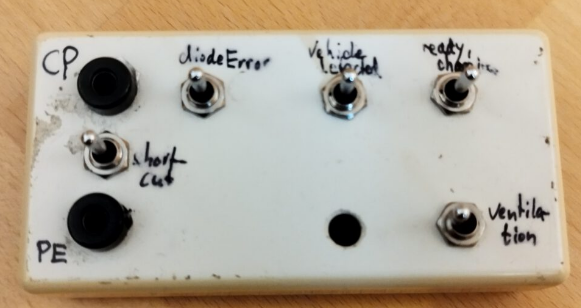
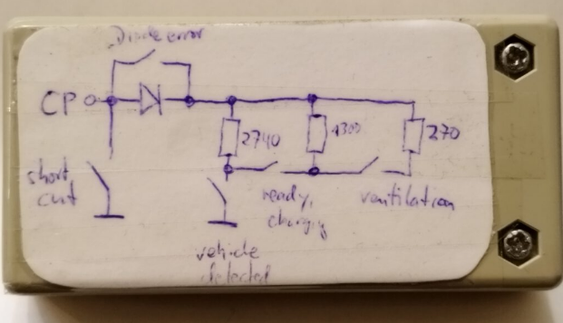
## Electric vehicle simulator
|
|
|
|
This device is able to convince an AC charger to deliver power, and also is needed to tell an DC charger, that a car is connected. By closing the "vehicle detected" switch, we pull the CP from 12V to 9V, and the charger will switch to the 5% PWM and starts listening to SLAC parameter request messages. (If DieterLV is controlling the CP, we do not need the EV simulator anymore.)
|
|
|
|
|
|
|
|
|
|
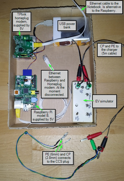
## Combination of EV simulator, HomePlug modem and Raspberry
|
|
|
|
|
|
|
|
## Connecting to a real-world charger
|
|
|
|
|
|
|